Verifying and Analyzing Ethernet Switching A Cisco Catalyst switch comes from the factory able to switch frames. All you’ve got to do is connect the facility cable, connect the Ethernet cables, and therefore the switch starts switching incoming frames. Connect multiple switches together, and that they are able to forward frames between the switches also . and therefore the big reason behind this default behavior has to do with the default settings on the switches.
Cisco Catalyst switches come able to get busy switching frames due to settings like these:
- The interfaces are enabled by default, able to start working once a cable is connected.
- All interfaces are assigned to VLAN 1.
- 10/100 and 10/100/1000 interfaces use autonegotiation by default.
- The MAC learning, forwarding, flooding logic all works by default.
- STP is enabled by default.
This second section of the chapter examines how switches will work with these default settings, showing the way to verify the Ethernet learning and forwarding process.
Also Read : Ethernet LAN Overview and Types of Ethernet LAN
Demonstrating MAC Learning
To see a switches MAC address table, use the show mac address-table command. With no additional parameters, this command lists all known MAC addresses within the MAC table, including some overhead static MAC addresses that you can ignore. to ascertain all the dynamically learned MAC addresses only, instead use the show mac address-table dynamic command. The examples during this chapter use almost no configuration, as if you only unboxed the switch once you first purchased it. For the examples, the switches haven’t any configuration aside from the hostname command to line a meaningful hostname. Note that to do this in lab, all I did was
- Use the erase startup-config EXEC command to erase the startup-config file
- Use the delete vlan.dat EXEC command to delete the VLAN configuration details
- Use the reload EXEC command to reload the switch (thereby using the empty startupconfig, with no VLAN information configured)
- Configure the hostname SW1 command to line the switch hostname
Once done, the switch starts forwarding and learning MAC address, as demonstrated in Example 7-1.
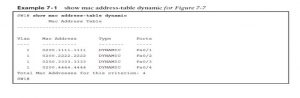
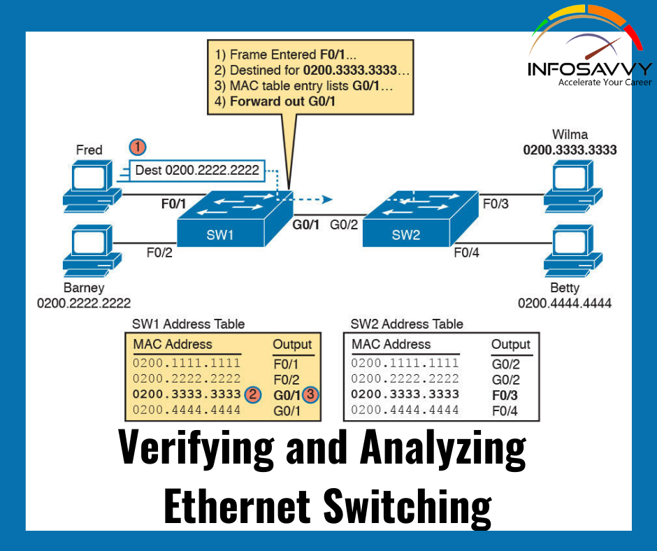
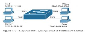
First, focus on two columns of the table: the Mac Address and Ports columns of the table. The values should look familiar: they match the earlier single-switch example, as repeated here as Figure 7-9. Note the four MAC addresses listed, along with their matching ports, as shown in the figure.
Next, look at the Type field in the header. The column tells us whether the MAC address was learned by the switch as described earlier in this chapter. You can also statically predefine MAC table entries using a couple of different features, including port security, and those would appear as Static in the Type column. Finally, the VLAN column of the output gives us a chance to briefly discuss how VLANs impact switching logic. LAN switches forward Ethernet frames inside a VLAN. What that means is if a frame enters via a port in VLAN 1, then the switch will forward or flood that frame out other ports in VLAN 1 only, and not out any ports that happen to be assigned to another VLAN. Chapter 11, “Implementing Ethernet Virtual LANs,” looks at all the details of how switches forward frames when using VLANs.
Switch Interfaces
The first example assumes that you installed the switch and cabling correctly, and that the switch interfaces work. Once you do the installation and connect to the Console, you can easily check the status of those interfaces with the show interfaces status command, as shown in Example 7-2.
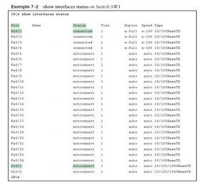
Focus on the port column for a moment. As a reminder, Cisco Catalyst switches name their ports based on the fastest specification supported, so in this case, the switch has 24 interfaces named Fast Ethernet, and two named Gigabit Ethernet. Many commands abbreviate those terms, this time as Fa for Fast Ethernet and Gi for Gigabit Ethernet. (The example happens to come from a Cisco Catalyst switch that has 24 10/100 ports and two 10/100/1000 ports.)
The Status column of course tells us the status or state of the port. In this case, the lab switch had cables and devices connected to ports F0/1–F0/4 only, with no other cables connected. As a result, those first four ports have a state of connected, meaning that the ports have a cable and are functional. The notconnect state means that the port is not yet functioning. It may mean that there is no cable installed, but other problems may exist as well. (The section “Analyzing Switch Interface Status and Statistics,” in Chapter 12, “Troubleshooting Ethernet LANs,” works through the details of what causes a switch interface to fail.)
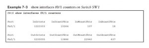
The show interfaces command has a large number of options. One particular option, the counters option, lists statistics about incoming and outgoing frames on the interfaces. In particular, it lists the number of unicast, multicast, and broadcast frames both the in and out direction, and a total byte count for those frames. Example 7-3 shows an example, again for interface F0/1 .
Questions related to this topic
- Do switch interfaces have MAC addresses?
- Does it matter what port you use on a switch?
- How do switches make forwarding decisions?
- How do you configure a switch port to be active accessible?
This Blog Article is posted by
Infosavvy, 2nd Floor, Sai Niketan, Chandavalkar Road Opp. Gora Gandhi Hotel, Above Jumbo King, beside Speakwell Institute, Borivali West, Mumbai, Maharashtra 400092
Contact us – www.info-savvy.com